- 您现在的位置:买卖IC网 > Sheet目录317 > C8051F380-TB (Silicon Laboratories Inc)DEV KIT FOR C8051F38X
C8051F380/1/2/3/4/5/6/7/C
26.3. Timer 3
Timer 3 is a 16-bit timer formed by two 8-bit SFRs: TMR3L (low byte) and TMR3H (high byte). Timer 3 may
operate in 16-bit auto-reload mode, (split) 8-bit auto-reload mode, USB Start-of-Frame (SOF) capture
mode, or Low-Frequency Oscillator (LFO) Rising Edge capture mode. The Timer 3 operation mode is
defined by the T3SPLIT (TMR3CN.3), T3CE (TMR3CN.4) bits, and T3CSS (TMR3CN.1) bits.
Timer 3 may be clocked by the system clock, the system clock divided by 12, or the external oscillator
source divided by 8. The external clock mode is ideal for real-time clock (RTC) functionality, where the
internal oscillator drives the system clock while Timer 3 (and/or the PCA) is clocked by an external preci-
sion oscillator. Note that the external oscillator source divided by 8 is synchronized with the system clock.
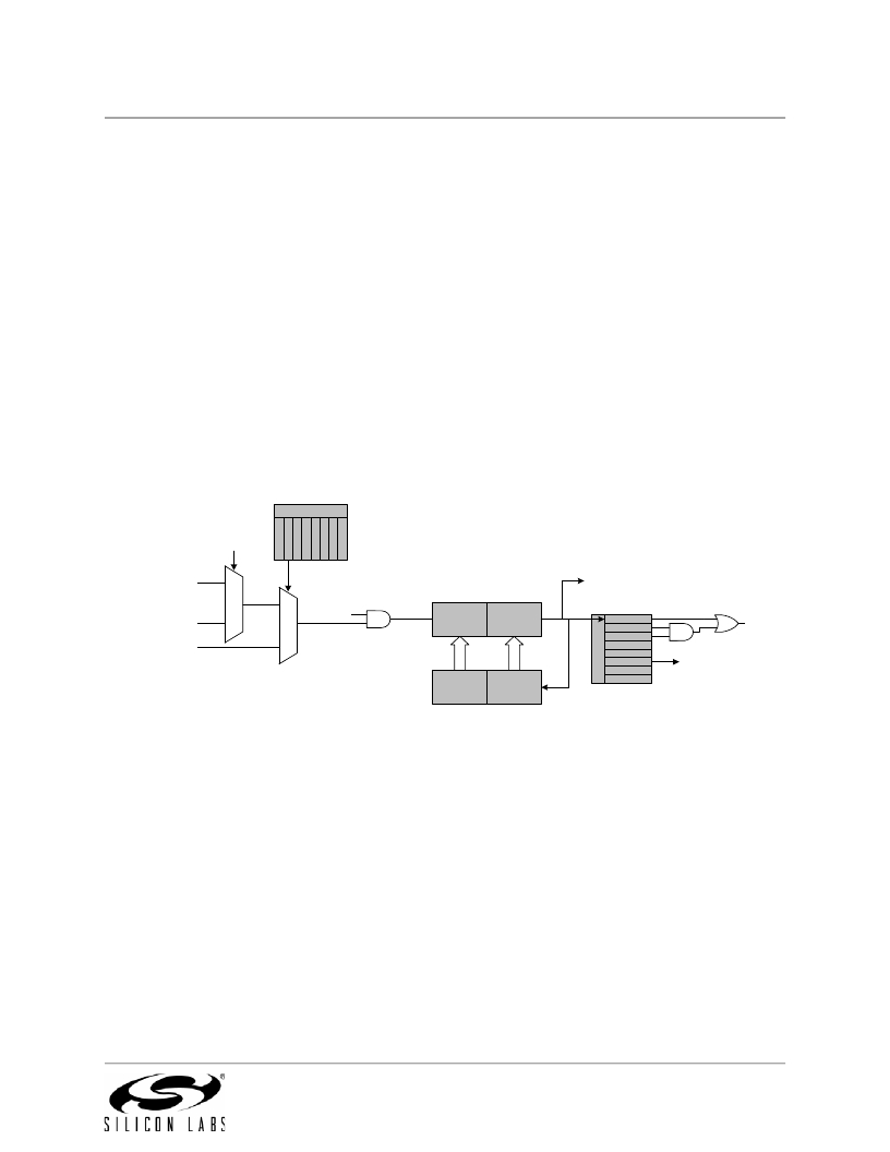
26.3.1. 16-bit Timer with Auto-Reload
When T3SPLIT (TMR3CN.3) is zero, Timer 3 operates as a 16-bit timer with auto-reload. Timer 3 can be
clocked by SYSCLK, SYSCLK divided by 12, or the external oscillator clock source divided by 8. As the
16-bit timer register increments and overflows from 0xFFFF to 0x0000, the 16-bit value in the Timer 3
and the Timer 3 High Byte Overflow Flag (TMR3CN.7) is set. If Timer 3 interrupts are enabled (if EIE1.7 is
set), an interrupt will be generated on each Timer 3 overflow. Additionally, if Timer 3 interrupts are enabled
and the TF3LEN bit is set (TMR3CN.5), an interrupt will be generated each time the lower 8 bits (TMR3L)
overflow from 0xFF to 0x00.
CKCON
T T T T T T S
S
T3XCLK
3 3 2 2 1 0 C
M M M M M M A
C
A
H L H L
1
0
SYSCLK / 12
0
To ADC
External Clock / 8
SYSCLK
1
0
1
TR3
TCLK
TMR3L TMR3H
TMR3RLL TMR3RLH
TF3H
TF3L
TF3LEN
T3CE
T3SPLIT
TR3
T3CSS
T3XCLK
Interrupt
Reload
Figure 26.8. Timer 3 16-Bit Mode Block Diagram
Rev. 1.4
281
发布紧急采购,3分钟左右您将得到回复。
相关PDF资料
C8051F912DK
KIT DEV FOR C8051F91X/C8051F90X
C8051F930-TB
BOARD TARGET/PROTO W/C8051F930
C8051T610DB24
DAUGHTER BOARD T610 24QFN SOCKET
C8051T630DB20
BOARD SOCKET DAUGHTER 20-QFN
CAN-100
BOARD EVAL RS232 100QFP
CANADAPT28
KIT ADAPTER CANDEMOBOARD 28PLCC
CAT24AA01WI-GT3
IC EEPROM SERIAL 1KB I2C 8SOIC
CAT24AA02WI-G
IC EEPROM SERIAL 2KB I2C 8SOIC
相关代理商/技术参数
C8051F381
制造商:SILABS 制造商全称:SILABS 功能描述:USB DRIVER CUSTOMIZATION
C8051F381-GM
功能描述:8位微控制器 -MCU USB-64K-Flash
RoHS:否 制造商:Silicon Labs 核心:8051 处理器系列:C8051F39x 数据总线宽度:8 bit 最大时钟频率:50 MHz 程序存储器大小:16 KB 数据 RAM 大小:1 KB 片上 ADC:Yes 工作电源电压:1.8 V to 3.6 V 工作温度范围:- 40 C to + 105 C 封装 / 箱体:QFN-20 安装风格:SMD/SMT
C8051F381-GMR
功能描述:8位微控制器 -MCU USB-Flash-64k-ADC RoHS:否 制造商:Silicon Labs 核心:8051 处理器系列:C8051F39x 数据总线宽度:8 bit 最大时钟频率:50 MHz 程序存储器大小:16 KB 数据 RAM 大小:1 KB 片上 ADC:Yes 工作电源电压:1.8 V to 3.6 V 工作温度范围:- 40 C to + 105 C 封装 / 箱体:QFN-20 安装风格:SMD/SMT
C8051F381-GQ
功能描述:8位微控制器 -MCU USB-64K-Flash
RoHS:否 制造商:Silicon Labs 核心:8051 处理器系列:C8051F39x 数据总线宽度:8 bit 最大时钟频率:50 MHz 程序存储器大小:16 KB 数据 RAM 大小:1 KB 片上 ADC:Yes 工作电源电压:1.8 V to 3.6 V 工作温度范围:- 40 C to + 105 C 封装 / 箱体:QFN-20 安装风格:SMD/SMT
C8051F381-GQR
功能描述:8位微控制器 -MCU USB-Flash-64k-ADC RoHS:否 制造商:Silicon Labs 核心:8051 处理器系列:C8051F39x 数据总线宽度:8 bit 最大时钟频率:50 MHz 程序存储器大小:16 KB 数据 RAM 大小:1 KB 片上 ADC:Yes 工作电源电压:1.8 V to 3.6 V 工作温度范围:- 40 C to + 105 C 封装 / 箱体:QFN-20 安装风格:SMD/SMT
C8051F382
制造商:SILABS 制造商全称:SILABS 功能描述:USB DRIVER CUSTOMIZATION
C8051F382-GQ
功能描述:8位微控制器 -MCU USB-Flash-32k-ADC
RoHS:否 制造商:Silicon Labs 核心:8051 处理器系列:C8051F39x 数据总线宽度:8 bit 最大时钟频率:50 MHz 程序存储器大小:16 KB 数据 RAM 大小:1 KB 片上 ADC:Yes 工作电源电压:1.8 V to 3.6 V 工作温度范围:- 40 C to + 105 C 封装 / 箱体:QFN-20 安装风格:SMD/SMT
C8051F382-GQR
功能描述:8位微控制器 -MCU USB-Flash-32k-ADC RoHS:否 制造商:Silicon Labs 核心:8051 处理器系列:C8051F39x 数据总线宽度:8 bit 最大时钟频率:50 MHz 程序存储器大小:16 KB 数据 RAM 大小:1 KB 片上 ADC:Yes 工作电源电压:1.8 V to 3.6 V 工作温度范围:- 40 C to + 105 C 封装 / 箱体:QFN-20 安装风格:SMD/SMT
